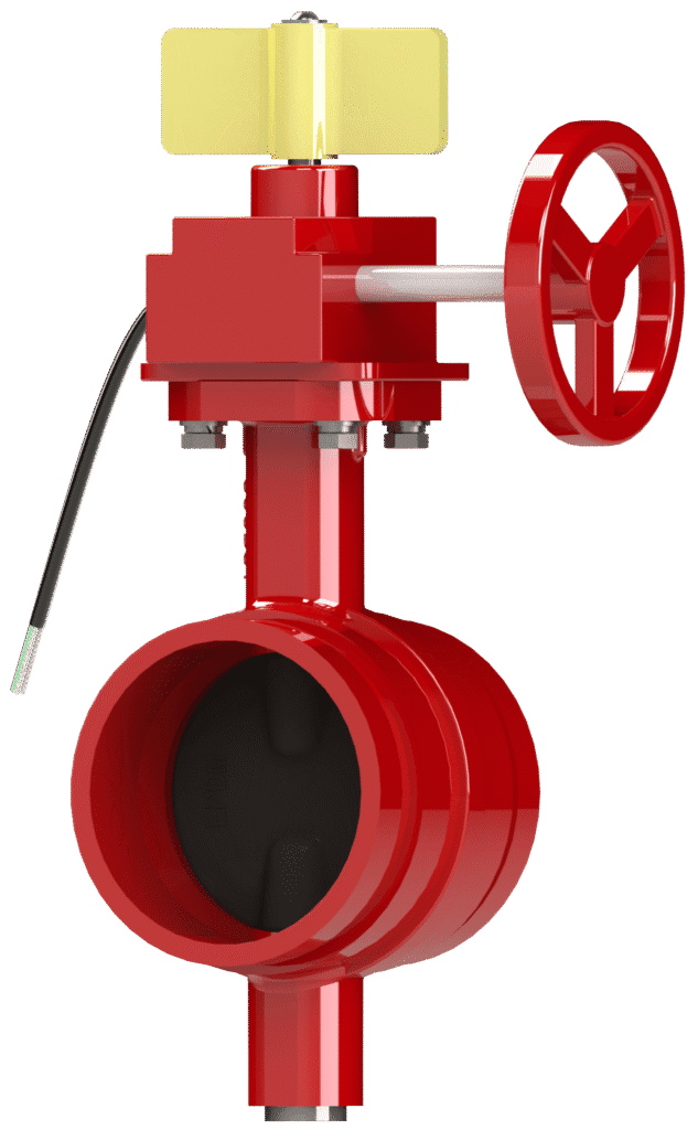
Butterfly Valve Grooved End Model 240G
The Century Model 240G is a quarter-turn isolation valve featuring grooved-end connections designed for use with mechanical couplings. This design allows for rapid, flame-free installation and provides some accommodation for pipeline movement and vibration. A gear operator provides low-torque actuation, and the integrated supervisory switch monitors the valve’s position for remote signaling to a fire alarm control panel.
Key Features: UL Listed, FM Approved, Grooved Ends for Fast Installation, Gear Operator with Supervisory Switch, EPDM Encapsulated Disc.
Primary Use: System control and isolation in fire sprinkler rooms, riser assemblies, and sectional control applications.
Widely used across various sectors, including: Commercial Construction, Warehousing, Data Centers, Industrial Facilities, and Retrofit Projects.
Information
Proper Storage:
If storage is required, keep the valve in a cool, dry environment with end protectors in place to prevent debris from entering the valve. Prior to installation, re-inspect the unit to verify its condition.
Inspect for Shipping Damage:
- Visually inspect the entire valve assembly for any cracks, dents, or other damage sustained during transit.
- Subsequently, operate the handwheel through one full cycle (open to close and back) to confirm the smooth mechanical action of the Shaft (Item 7) and Disc (Item 8).
Verify External Components:
- Confirm that all bolts and nuts on the gear operator (Item 16) and supervisory switch are secure and have not loosened during shipment.
Handling Notice:
- This is a precision-engineered valve. To prevent damage and ensure proper function, handle with care at all times to protect the EPDM sealing surfaces on the Disc (Item 8).
- Lift only by the valve Body (Item 1).
- Never lift, carry, or support the valve by the handwheel or gear operator. Applying force to these components can damage the operator and compromise valve alignment.
Verify Valve Specifications:
- Before installation, confirm the valve’s model (240G), size, and pressure rating match the requirements listed in the system engineering plans.
Prepare Mating Surfaces:
- Thoroughly clean the valve’s grooved ends and the mating pipe grooves. Ensure all surfaces are completely free of dirt, rust, debris, and any foreign materials that could compromise the integrity of the seal.
Select and Inspect Gasket:
- Use only grooved coupling gaskets rated for the system’s maximum operating pressure and temperature. Visually inspect the gasket to confirm it is free from defects. Do not use a damaged gasket.
Align Grooves:
- Position the valve between the pipe ends, ensuring the pipe faces are parallel and concentric.
- Caution: Misalignment, especially in existing pipework, can impose dangerous stress on the valve Body (Item 1) and lead to damage or failure. The adjacent piping should be properly supported to prevent excessive stress on the valve.
Install Grooved Coupling:
- Install the two halves of an approved grooved coupling around the gasket and into the pipe/valve grooves. Insert bolts and hand-tighten the nuts.
- Tighten the nuts incrementally using an alternating pattern to ensure uniform pressure on the gasket. Repeat the sequence until the coupling housings achieve metal-to-metal contact as specified by the coupling manufacturer.
System Flushing:
- After completing the installation and before pressurizing the system, thoroughly flush the interior of the valve and piping to remove all installation debris.
WARNING: All electrical wiring must be performed by a qualified electrician in accordance with all applicable local and national electrical codes. Disconnect power source before wiring to prevent electrical shock.
Contact Rating: 5A 250VAC
Opening Procedure:
- To open the valve, rotate the handwheel counterclockwise until it reaches a firm mechanical stop and the position indicator shows ‘OPEN’.
- It is recommended to then turn the handwheel clockwise approximately one-half turn. This practice prevents thermal binding and eases future operation.
Closing Procedure:
- To close the valve, rotate the handwheel clockwise until it reaches a firm mechanical stop and the position indicator shows ‘SHUT’.
Operational and Safety Notices:
- Prohibited Practices: Never use extension bars (“cheater bars”) or other leverage devices on the handwheel. Applying excessive force can damage the gear operator, Shaft (Item 7), and internal components. Use of excessive force violates all warranties, express or implied.
- On/Off Service Only: This valve is designed exclusively for on/off service. Do not use this valve for regulating or throttling flow, as this will cause turbulent flow that can rapidly erode and damage the Disc (Item 8) and its EPDM seal.
- Flow Direction: The valve is bi-directional and may be installed with flow in either direction.
- Water Hammer: The slow-close gear operator (Item 16) is designed to minimize water hammer in the system.
Maintenance Overview:
Century butterfly valves require no regular lubrication or internal maintenance. However, an annual inspection is required to ensure proper operation.
Pre-Maintenance Safety:
- Before any inspection or maintenance, ensure the line is fully depressurized.
Annual Inspection:
- Visually check for any signs of leakage at the grooved pipe connections and at the body-to-operator connection.
- Operate the valve through one full open/close cycle to verify smooth operation.
- If the valve closes with difficulty, it is likely due to debris in the sealing area. Open the valve again and re-close it. Never force the valve shut.
System Pressure Testing:
- When pressure testing the piping system, ensure the valve Disc (Item 8) is in the FULLY OPEN position to equalize pressure across the disc and prevent damage.
By following these maintenance steps, your Century butterfly valve will remain in proper working condition and ready to provide long and reliable service.
Please contact us at sales@centuryvalves.com for all your valve and hydrant needs.
| Model 240 G | ||
|---|---|---|
| Butterfly Valve Grooved End | ||
| Connections | Grooved | |
| Sizes | 2″, 2 1/2″, 3″, 4″, 6″, 8″, 10″, 12″ | |
| Approvals | UL 1091, FM1112 | |
| Design Standard | MSS-SP-67 | |
| Grooved Dimensions | AWWA C606 | |
| Coating | Fusion Bond Epoxy interior and exterior to suit AWWA C550 Standard | |
| Pressure Rating | 2″ ~ 12″ @ 300psi | |
| Temperature | -10°C to 120°C | 14°F to 248°F |
Certifications


We are ready to assist you
We are ready to assist you / Have questions or need support? Our team is ready to assist with your next project.