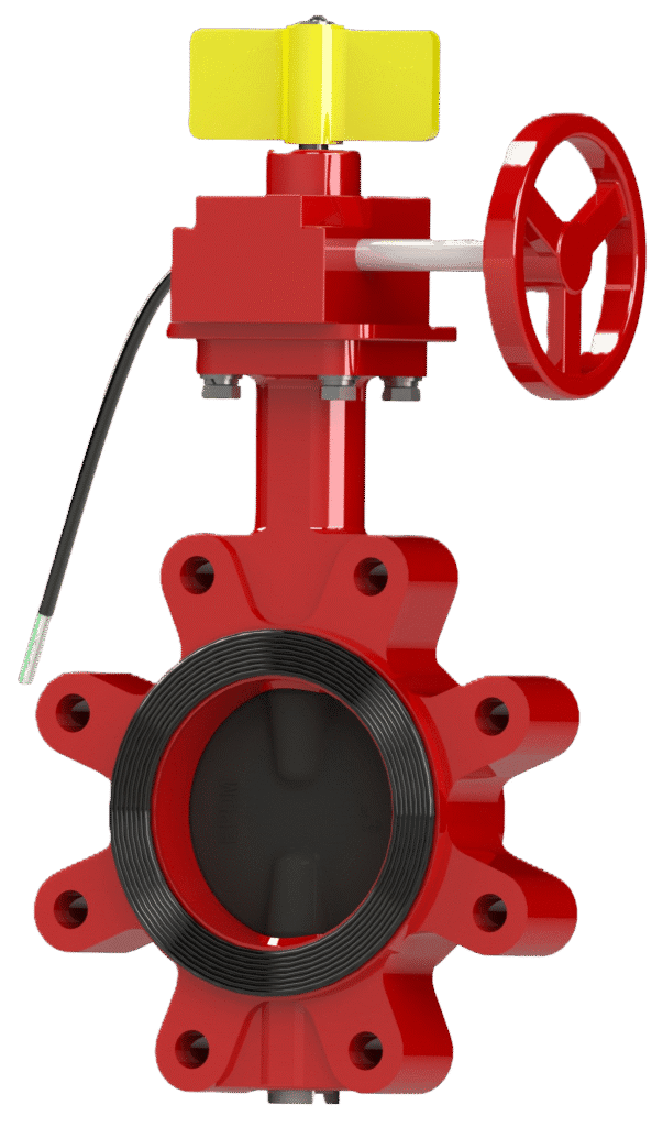
Butterfly Valve Lug End Model 240L
The Century Model 240L is a lug type butterfly valve engineered for dead-end service. Its body features threaded bolt holes (lugs) that allow each connecting flange to be bolted independently to the valve. This design permits the safe removal of downstream piping for equipment maintenance while the valve remains under pressure from the upstream side. An integrated supervisory switch provides remote position monitoring.
Key Features: UL Listed, FM Approved, Rated for Dead-End Service, Full Lug Body, Integrated Supervisory Switch.
Primary Use: Isolation of pumps, backflow preventers, and other equipment requiring maintenance; ideal for system sectionalizing and terminal connections.
Widely used across various sectors, including: Industrial Processing Plants, Power Generation, Chemical Facilities, Marine Applications, and Critical Infrastructure.
Information
Proper Storage:
If storage is required, keep the valve in a cool, dry environment with end protectors in place. Prior to installation, re-inspect the unit to verify its condition.
- Inspect for Shipping Damage:
- Visually inspect the entire valve assembly for any cracks, dents, or other damage sustained during transit.
- Operate the handwheel through one full cycle (from OPEN to SHUT and back) to confirm the smooth mechanical action of the Shaft (Item 7) and Disc (Item 8).
- Verify External Hardware:
- Confirm that all bolts and nuts on the Electrical Turbine Box (Item 16) and supervisory switch are secure and have not loosened during shipment.
Handling Notice:
- Handle with care at all times to protect the EPDM sealing surfaces on the Disc (Item 8).
- Lift only by the valve Body (Item 1).
- Never lift, carry, or support the valve by the handwheel or gear operator. Applying force to these components can damage the operator and compromise valve alignment.
Verify Valve Specifications:
Before installation, confirm that the valve’s model (240L), size, and pressure rating match the requirements listed in the system engineering plans.
Prepare Mating Surfaces:
Thoroughly clean the valve faces and the mating pipe flanges. Ensure all surfaces are completely free of dirt, rust, debris, and any foreign materials that could compromise the integrity of the seal.
Select and Inspect Gaskets:
Use two new gaskets rated for the system’s maximum operating pressure and temperature. Visually inspect the gaskets to confirm they are free from defects. Do not use a damaged gasket.
Valve Installation:
- CRITICAL: Ensure the Disc (Item 8) is in the slightly open position (approx. 10°) before installation. This prevents the disc edge from being pinched or damaged by the pipe flanges during installation.
- Align the piping and position the lug valve against one of the pipe flanges, using two bolts for temporary alignment.
- Place a gasket between the valve and the flange.
- Insert and tighten the first set of bolts, connecting the valve securely to the first pipe flange.
- Position the second pipe flange and gasket against the opposite side of the valve.
- Insert and tighten the second, separate set of bolts.
- Tighten all bolts incrementally using a star/crisscross pattern to their required torque value.
NOTE – DEAD-END SERVICE: Lug-style valves ARE suitable for dead-end service. This means that with the valve closed and the upstream side under pressure, the downstream piping can be safely removed for maintenance, as the valve Body (Item 1) remains securely bolted to the upstream flange.
System Flushing:
After completing the installation and before pressurizing the system, thoroughly flush the interior of the valve and piping to remove all installation debris.
WARNING: All electrical wiring must be performed by a qualified electrician in accordance with all applicable local and national electrical codes. Disconnect power source before wiring to prevent electrical shock.
Contact Rating: 5A 250VAC
Operation:
- Opening: Rotate the handwheel counter-clockwise until it stops. It is recommended to then turn the handwheel clockwise approximately one-half turn to prevent thermal binding.
- Closing: Rotate the handwheel clockwise until it reaches a firm mechanical stop.
Safety Notices:
- Prohibited Practices: Never use “cheater bars” or other leverage devices on the handwheel.
- On/Off Service Only: Do not use this valve for throttling.
Pre-Maintenance Safety: Before any inspection, ensure the line is fully depressurized.
Annual Inspection:
- Visually check for any signs of leakage at the flange connections and at the Body (Item 1)-to-operator connection.
- Operate the valve through one full open/close cycle to verify smooth operation.
System Pressure Testing: When pressure testing the piping system, ensure the valve Disc (Item 8) is in the FULLY OPEN position to equalize pressure and prevent damage.
By following these maintenance steps, Century butterfly valve will remain in proper working condition and ready to provide long and reliable service.
Please contact us at sales@centuryvalves.com for all your valve and hydrant needs.
| Model 240 L | ||
|---|---|---|
| Butterfly Valve Lug End | ||
| Connections | Lug | |
| Sizes | 2″, 2 1/2″, 3″, 4″, 6″, 8″, 10″, 12″ | |
| Approvals | UL 1091, FM1112 | |
| Design Standard | MSS-SP-67 | API 609 |
| Coating | Fusion Bond Epoxy interior and exterior to suit AWWA C550 Standard | |
| Pressure Rating | 2″ ~ 12″ @ 300psi | |
| Temperature | -10°C to 120°C | 14°F to 248°F |
Certifications


We are ready to assist you
We are ready to assist you / Have questions or need support? Our team is ready to assist with your next project.