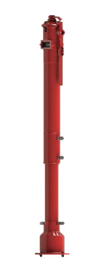
Vertical Indicator Post 14″ ~ 24″ Model G545
The Century Model G545 is a geared indicator post designed for the operation and status verification of large-diameter, non-rising stem (NRS) gate valves. An important aspect of this product’s design is the integrated gear operator housed at the base of the post, which significantly reduces the input torque required to operate large valves with ease and precision.
This mechanism translates the rotational input from the operating wrench into the linear motion that drives the internal “OPEN” and “SHUT” targets, which are visible through a sealed window. The telescoping standpipe design allows for adjustable bury depth to match the finished grade, providing reliable, low-effort, above-ground operation for critical fire main valves.
Key Features: UL Listed, FM Approved, Integrated Gear Operator for Torque Reduction, High-Visibility “OPEN/SHUT” Targets, Adjustable Bury Depth, Lockable Operating Wrench.
Primary Use: Operation and status indication for large-diameter or high-pressure underground fire main valves, where the operating torque of a standard valve would be too high.
Widely used across various sectors, including: Large-Scale Industrial Facilities, Municipal Water Grids, Airport Infrastructure, and Major Commercial Developments.
Information
Inspect for Shipping Damage
- Visually inspect the entire assembly, including the Body and top section, for any cracks, dents, or damage sustained during transit. Check that the Window Glass is intact.
Verify External Hardware
- Confirm that all external fasteners, such as Hex Cap Screws and Hex Nuts, are secure and have not loosened during shipment. Ensure the Locking Wrench is present and undamaged.
Preliminary Functional Check
- Before installation, gently turn the Operating Nut a few rotations to confirm the internal mechanism moves smoothly. Return it to its original position after the check.
Handling Notice
- This is a precision-engineered indicator post. To prevent damage and ensure proper function:
- Handle with care at all times to protect the window, indicator mechanism, and external components.
- Lift the assembly only by its main Body or the Base Flange.
- Never lift, carry, or support the assembly by the Stand Pipe or the top operating mechanism.
Preliminary Disassembly
- Before connecting to the valve, partially disassemble the post:
- Remove the Locking Wrench.
- Loosen the Hex Cap Screw and Hex Nut, and set aside the complete top assembly.
- Loosen the bolts connecting the main Body, Stand Pipe, and Base Flange.
Mount the Base Flange
- Ensure the underground gate valve is in the fully open position.
- Attach the Base Flange of the indicator post to the post flange of the gate valve using the specified mounting bolts.
Adjust for Bury Depth
- Reassemble the Stand Pipe and Body. Adjust their height until the “GROUND LINE” mark on the post aligns with the finished grade.
- Fully tighten all the hardware to lock the height in place.
Adjust the Square Stem
- Calculate and, if necessary, cut the square Stem to the required length based on the final bury depth. Ensure the cut end is free of burrs.
- Lower the Stem through the post to engage the operating nut of the gate valve.
Adjust the Indicator Targets
- With the gate valve fully open, adjust the ‘OPEN’ Target so it is centered in the window.
- Position the ‘SHUT’ Target at the correct distance below the ‘OPEN’ plate, corresponding to the gate valve’s size.
- Secure both plates to the Target Carrier Nut.
Final Assembly and Testing
- Reinstall the complete top assembly onto the Body and secure it with the Hex Cap Screw and Hex Nut.
- Cycle the valve from fully open to fully closed using the Locking Wrench. Confirm that the ‘OPEN’ and ‘SHUT’ targets align perfectly in the window at each position. Readjust if necessary.
Opening Procedure
- To open the valve, rotate the Locking Wrench counterclockwise until the post’s internal mechanism stops and the ‘OPEN’ Target is centered.
- It is recommended to then turn the wrench clockwise one-half turn for optimal alignment.
Closing Procedure
- To close the valve, rotate the Locking Wrench clockwise until the internal mechanism stops and the ‘SHUT’ Target is centered.
Lubrication
- At least once per year, lubricate the bearing surfaces within the top assembly by adding several drops of suitable oil into the hole on top of the Operating Nut.
- Maintenance on the underground gate valve (such as gland packing or internal inspection) should be performed according to that specific product’s maintenance manual.
By following these maintenance steps, your vertical post indicator will remain in proper working condition and ready to provide service when needed most.
Please contact us at sales@centuryvalves.com for all your valves and vertical post indicator needs.
| Model G545 | |||
|---|---|---|---|
| Vertical Indicator Post 14″ ~ 24″ | |||
| Connections | Flange | ||
| Sizes | 14″ ~ 24″ | ||
| Approvals | UL 789, FM 1110 | ||
| Design Standard | NFPA 24 | ||
| Coating | Fusion Bond Epoxy interior and exterior to suit AWWA C550 Standard | ||
Certifications


We are ready to assist you
We are ready to assist you / Have questions or need support? Our team is ready to assist with your next project.