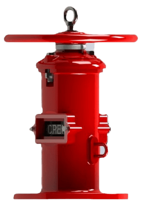
Wall Indicator Post Model W540
The Century Model W540 is a wall-mounted indicator post designed to operate and display the status of an NRS gate valve located on the opposite side of a wall. The assembly’s stem passes through the wall to engage the valve’s operating nut, translating the handwheel’s rotational force into valve actuation. Simultaneously, the mechanism drives “OPEN” and “SHUT” targets for clear, at-a-glance position confirmation through a sealed window, making it ideal for fire pump rooms and interior sectional control.
Key Features: UL Listed, FM Approved, Wall-Mount Design, Clear “OPEN/SHUT” Visual Indicator, Handwheel Operation.
Primary Use: Remote operation and status indication for NRS valves controlling fire mains from within a building or passing through interior walls.
Widely used across various sectors, including: Fire Pump Rooms, Mechanical Rooms in Commercial Buildings, Industrial Facilities, and Institutional Campuses.
Information
Proper Storage
If storage is required, keep the Wall Post Indicator in a cool, dry environment. Before installation, re-inspect the unit to verify that its condition has not changed.
Inspect for Shipping Damage
- Visually inspect the entire post assembly for any cracks, dents, or other damage sustained during transit.
- Subsequently, operate the Handwheel through several rotations in both directions to confirm the smooth mechanical action of the internal Operating Nut.
Verify External Hardware
- Confirm that all external bolts and nuts, including the Hex Cap Screws on the Cover, are secure and have not loosened during shipment.
Handling Notice
- This is a heavy-duty assembly. Handle it with care at all times.
- Lift the unit only by the main Body.
- Never lift, carry, or support the post by its Handwheel. Applying force to the handwheel can damage the operating mechanism.
CRITICAL NOTE: Before beginning the installation, ensure the associated non-rising stem gate valve is in the FULLY OPEN position.
Create the Wall-Through Hole
- Make a clearance hole through the mounting wall that is a minimum of 4.7 inches (120mm) and a maximum of 7.1 inches (180mm) in diameter.
- This hole must be concentric with the 2-inch square operating nut of the NRS gate valve.
- Recommendation: A 4-inch (114.3mm OD) pipe sleeve can be used to line the hole. This sleeve will fit snugly into the machined recess on the flange of the wall post Body.
Drill the Mounting Holes
- Using the post’s flange as a template or the specified 10.5-inch (267mm) bolt circle, drill four mounting holes through the wall using a 3/4-inch (19mm) drill bit.
Mount the Wall Post Body
- Securely bolt the flange of the Body to the wall using four appropriately sized bolts and anchors (to be provided by the customer).
Remove the Cover
- With the Body now securely mounted, remove the Hex Cap Screws and Square Nuts.
- Carefully slide the Cover off the body to expose the internal mechanism.
Insert and Measure the Stem Assembly
- Assemble the Stem, Crane Coupling, and Cotter Pin.
- Slide this assembly through the body and the wall until the Crane Coupling fully engages with the operating nut of the NRS gate valve.
- With the coupling fully engaged, make a clear mark on the Stem at a point between 1.25 inches (32mm) below and 2 inches (50mm) above the top surface of the wall post body.
Cut the Stem Rod
- Remove the stem assembly. Carefully and squarely cut the Stem at the mark made in the previous step.
- De-burr the cut end to ensure smooth operation.
Adjust the Target Plates
- Loosen the Hex Cap Screw and Hex Nut that secure the Target plates.
- With the NRS gate valve still in the FULLY OPEN position, slide the “OPEN” target plate until it is perfectly centered in the Window Glass.
- Manually close the NRS gate valve completely. Slide the “SHUT” target plate until it is centered in the window.
- Securely tighten the Hex Cap Screw and Hex Nut to lock the targets in place.
Re-assemble and Verify
- Insert the cut stem assembly and the Cover back onto the body. Ensure the ears on the Target Carrier Nut fit correctly into the grooves on the body.
- Re-install and tighten the Hex Cap Screws and Square Nuts.
- Using the Handwheel, operate the valve from fully open to fully closed. Verify that the “OPEN” and “SHUT” targets align correctly in the window at each end of the valve’s travel. Adjust if necessary.
Opening Procedure
To open the valve, rotate the Handwheel counterclockwise until it reaches a firm mechanical stop and the visual indicator clearly reads ‘OPEN’. It is recommended to then turn the handwheel clockwise approximately one-half turn. This practice prevents thermal binding of the Stem and eases future operation.
Closing Procedure
To close the valve, rotate the Handwheel clockwise until it reaches a firm mechanical stop and the visual indicator clearly reads ‘SHUT’.
Operational and Safety Notices
- Prohibited Practices: Never use extension bars (“cheater bars”) or other leverage devices on the handwheel. Applying excessive force can damage the post mechanism, operating Stem, and internal valve components, and will void the product warranty.
- On/Off Service Only: This indicator post operates an NRS gate valve, which is intended exclusively for on/off service. It must be used only in the fully open or fully closed position. Do not use this device to regulate or throttle flow, as this will cause severe damage to the gate valve’s wedge and seats.
- Visual Verification: Always confirm the valve’s status by checking the visual indicator window after operation.
Lubrication
At least once a year, apply several drops of oil to the bearing through the oil hole located on top of the Operating Nut. This ensures smooth operation and protects against corrosion.
By following these guidelines, your Century Wall Indicator Post will provide long-term, reliable service. Please contact us at sales@centuryvalves.com for all your valves and hydrant needs.
| Model W540 | |
|---|---|
| Wall Indicator Post | |
| Connections | Flange |
| Approvals | UL 789, FM 1110 |
| Design Standard | NFPA 24 |
| Coating | Fusion Bond Epoxy interior and exterior to suit AWWA C550 Standard |
Certifications


We are ready to assist you
We are ready to assist you / Have questions or need support? Our team is ready to assist with your next project.