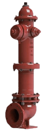
Dry Barrel Hydrant Model F600
The Century Model F600 is a dry barrel fire hydrant designed for service in climates subject to freezing temperatures. Its operating mechanism is located underground, where the main valve seals the hydrant from the water main. When the hydrant is closed, a drain valve automatically opens, allowing all water in the upper barrel to drain out, thus preventing damage from freezing. The hydrant features a traffic-rated safety flange designed to break away upon impact, protecting the main valve and underground piping.
Key Features: UL Listed, FM Approved, Dry Barrel Design (AWWA C502), Automatic Drain System, Traffic/Break-Away Safety Flange.
Primary Use: Reliable fire protection water access in regions with freezing weather conditions.
Widely used across various sectors, including: Municipal Waterworks, Commercial Real Estate, Industrial Complexes, and Suburban Developments.
Information
Storage and Initial Inspection
- If immediate installation is not possible, store the hydrant with the inlet facing downward. Inspect once again before use to confirm that no conditions have changed.
- Inspect the hydrant for signs of damage sustained during transit. Operate the Operating Nut fully in both directions to verify smooth movement and internal integrity.
- Check that all nozzles and their Hose Nozzle Caps, threaded joints, and external fittings are secure and have not loosened during transportation.
- After completing inspection and functional checks, confirm that the main valve is closed to prevent unintended flow when connected to the system.
Coordination with Water Mains
Ensure that the Century F600 hydrant installation is coordinated with the existing water mains to meet required fire flow capacities. Comply with local fire codes, municipal design standards, or relevant authority requirements.
Upright Installation
Position the Century F600 fire hydrant as vertically as possible, considering site conditions. Ensure the hydrant remains plumb to allow for proper operation and maintenance.
Setback Distance
Unless otherwise directed by local regulations, place the hydrant at least 2 feet (approximately 60 cm) back from the edge of the curb or roadway to ensure accessibility and protection.
Nozzle Orientation
Align the pumper nozzle to face the street to allow firefighters to connect to the hydrant quickly during emergencies.
Nozzle Height and Clearance
Install all outlet nozzles, especially the hose connections, at a minimum of 18 inches (46 cm) above finished grade. Keep the area around the nozzles clear of obstructions to ensure wrench access and cap removal.
Auxiliary Valve Installation
Install a 6” gate valve on the hydrant lead, as close to the main as practical, to allow for isolation during maintenance or emergencies. Provide appropriate thrust restraint, such as joint restraints or thrust blocks, to secure the connection without requiring shutdown of the main line.
Clean Piping Before Installation
Clear any debris or foreign material from the hydrant connection pipe before installing the Century F600 hydrant and its valve to prevent contamination and ensure proper function.
Secure Foundation
Mount the hydrant on a solid base, such as concrete or stone, to avoid settling strain on the riser or damage to the lead pipe. Use thrust restraint systems to prevent movement under pressure.
Drain Hole Protection
When placing concrete or other supports, do not obstruct the hydrant’s drain holes. Keep them clear for proper drainage.
Drainage Considerations
In locations with high water tables, plug the drain outlets to prevent groundwater from entering. Fully drain or pump the hydrant dry and mark it clearly to avoid freezing damage.
Drain Outlet Restrictions
Avoid connecting hydrant drain outlets to storm drains, sanitary sewers, or any domestic water systems.
Traffic Hydrants and Environmental Factors
Install traffic-rated hydrants per AWWA Manual M17 guidelines, taking into account soil conditions, frost depth, PVC piping, drainage capacity, and potential traffic loads.
Disinfection for Existing Mains
When connecting to existing pipelines, disinfect the Century F600 hydrant according to AWWA M17 guidelines before commissioning.
Debris Removal Before Disinfection
If contamination is suspected, disassemble the hydrant valve and seat, and flush the system through the gate valve before disinfecting.
Pressure Testing and Further Guidance
Refer to AWWA C600 and AWWA M17 for pressure testing procedures and additional technical specifications.
Note: Use calibrated torque tools to prevent over-tightening.
Shut Off Water Supply
Close the Century F600 Fire Hydrant gate valve to stop the water flow from the main pipe into the hydrant.
Relieve Internal Pressure
To safely relieve any residual pressure, remove one of the Hose Nozzle Caps. Turn the Operating Nut counterclockwise three full turns. After the water has stopped draining, fully close the hydrant by turning the Operating Nut clockwise until it gently stops.
Caution: Ensure all internal pressure is relieved before disassembly to avoid injury.
Apply Lubricant
Remove the top external Plug and apply manufacturer-recommended lubricant into the exposed cavity. This lubricates the Top Shaft and protects the O-rings inside the Cover from thread damage during removal.
Remove Top Components
Loosen and remove the Lock Nut and the Operating Nut. Keep the Antifriction Pad for reassembly.
Protect O-Ring During Cover Removal
Insert the protective sleeve with its chamfered end into the Top Shaft threads. This prevents damage to the O-Ring during Cover removal.
Cover Removal
Unbolt and gently lift off the Cover. Carefully remove the cover O-Ring from the Top Body.
Seat Wrench Setup
Remove the protective sleeve. Place the seat wrench bracket over the valve stem. Insert the T-handle seat wrench through the bracket until it engages the retaining pin in the rod. Tighten the bracket screw and rotate the wrench counterclockwise approximately seven full turns to disengage the internal rod assembly.
Extract Internal Components
Remove the seat wrench and bracket, then lift out the rod assembly. Disassemble and inspect parts such as the main valve, Tablet, Seat Ring, and seals. Replace any components that are worn or damaged.
Drain Valve and O-Ring Check
Inspect the Drain Valve Cover facings and all O-Rings for wear, cracking, or deformation. Replace as necessary before reassembly. Use spare O-Rings, as they may be easily damaged during disassembly.
Reassembly
Reinstall Internal Valve Components
Reassemble the valve components in reverse order of disassembly. Tighten the Tablet nut to the specified torque (approximately 100 ft-lb). Bend the Lock Washer to secure the nut.
Insert Rod Assembly
Lower the rod assembly back into the hydrant body carefully to avoid damaging the O-Rings. Use the seat wrench and bracket to torque the assembly into place (approximately 375 ft-lb).
Reinstall Cover and Seals
Install a new or inspected O-Ring into the flange groove. Reattach the Cover and bolts loosely at first, then tighten once everything is correctly aligned.
Reinstall Top Components
Remove the protective sleeve. Reinstall the Operating Nut and Antifriction Pad. Inspect the O-Ring of the Lock Nut; replace if necessary. Secure the Lock Nut and fully tighten all cover bolts.
NOZZLE REPLACEMENT
Remove Existing Nozzle
Unscrew the Hose Nozzle Cap (Item 10 or 44). Use the nozzle lock key and a hammer to remove the lock keys. Fit the nozzle wrench onto the nozzle with correct alignment.
Loosen Nozzle
Slide a sturdy extension (e.g., 3-ft. steel pipe) over the wrench handle for leverage. Loosen the nozzle by turning clockwise.
Note: reverse threads.
Install New Nozzle
Thread the new Hose Nozzle (Item 12 or 46) and Hose Nozzle Gasket (Item 11 or 45) into place counterclockwise. Hold the nozzle in alignment using the wrench and cap, and tighten to approximately 600 ft-lb. Remove the wrench and cap.
Lock Key Installation
Reinsert the lock keys between the nozzle lugs and the hydrant body using the key tool and hammer. Ensure proper seating and alignment. Perform a standard leak test to ensure proper sealing.
By following these maintenance steps, your hydrant will remain in proper working condition and ready to provide service when needed most.
Please contact us at sales@centuryvalves.com for all your hydrant needs.
| Model F600 | ||||||
|---|---|---|---|---|---|---|
| Dry Barrel Hydrant | ||||||
| Connections | Two hose nozzles 2 1/2″ NHT, One pumper nozzle 4 1/2″ NHT – Other configurations available | |||||
| Approvals |
|
|||||
| Design Standard | AWWA C502 | |||||
| Inlet | 6″ ANSI B16.1 flange or 6″ Mechanical Gasket according to AWWA C606 | |||||
| Flange Dimensions | Flange Dimensions per ANSI B16.1 Class 125 Flat Face | |||||
| Coating | Fusion Bond Epoxy interior and exterior to suit AWWA C550 Standard | |||||
| Pressure Rating | 250psi | |||||
| Temperature |
|
|||||
Certifications


We are ready to assist you
We are ready to assist you / Have questions or need support? Our team is ready to assist with your next project.