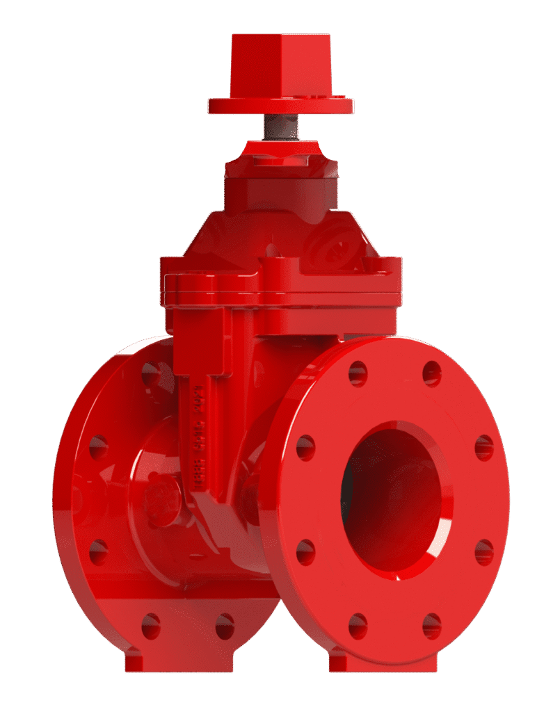
Non-Rising Stem (NRS) Gate Valve Model 201
The Century Model 201 is a Non-Rising Stem (NRS) gate valve designed for main shut-off service in fire protection systems. Its primary design feature is the non-rising stem, which confines all stem movement entirely within the valve body, making it ideal for underground installations or applications with vertical space limitations. The valve utilizes a fully EPDM-encapsulated ductile iron wedge to achieve a bubble-tight, bi-directional seal. A fusion-bonded epoxy coating on all interior and exterior surfaces provides superior corrosion resistance.
Key Features: UL Listed, FM Approved, NSF/ANSI/CAN 61, NSF/ANSI 372, Resilient Seated Wedge, Fusion Bonded Epoxy Coating (AWWA C550), Flanged Ends (ANSI B16.1), Low-Torque Operation.
Primary Use: Main water supply isolation for fire sprinkler systems, fire hydrants, and sectional control.
Widely used across various sectors, including: Commercial Real Estate, Industrial Manufacturing, Warehousing & Logistics, Data Centers, and Municipal Waterworks.”
Information
Proper Storage:
If storage is required, keep the valve upright in a clean, dry environment.
Prior to installation, inspect once again the unit to verify its condition has not changed.
Inspect for Shipping Damage:
Visually inspect the entire valve assembly for any cracks, dents, or other damage sustained during transit.
Subsequently, operate the Wrench Nut (Item 12) through its full range of motion in both directions to confirm smooth mechanical action and internal integrity.
Verify External Components:
Confirm that all bolts, plugs, and other external hardware are secure and have not loosened during shipment.
Handling Notice:
This is a precision-engineered valve. To prevent damage and ensure proper function:
- Handle with care at all times to protect sealing surfaces and external components.
- Lift only by the valve Body (Item 1).
- Never lift, carry, or support the valve by the Stem (Item 3) or the Wrench Nut (Item 12). Applying force to these components can damage the operating mechanism and compromise valve alignment.
Verify Valve Specifications:
Before installation, confirm that the valve’s model, size, pressure rating, and material specifications match
the requirements listed in the system engineering plans. Installing an incorrect valve can lead to system failure.
Prepare Mating Surfaces:
Thoroughly clean the valve flanges and both mating pipe flanges. Ensure all surfaces are completely free of dirt, rust, debris,
and any foreign materials that could compromise the integrity of the seal.
Select and Inspect Gasket:
Use only gaskets rated for the system’s maximum operating pressure and temperature. Before installation,
visually inspect the Gasket (Item 16) to confirm it is free from any defects, tears, or damage.
Do not use a damaged gasket.
Align Flanges:
Position the valve between the pipe flanges, ensuring the flange faces are parallel and concentric before making contact with the Gasket (Item 16).
(See AWWA C600: Figure 3, for mechanical-joint assembly).
Caution: Misalignment, especially when installing into existing pipework, can impose dangerous stress on the valve Body (Item 1) and lead to damage or failure.
Install and Tighten Bolting:
Install all specified bolts and nuts. Tighten the bolts incrementally using a star or crisscross pattern to ensure uniform pressure on the gasket.
Repeat the tightening sequence until all bolts have reached their required torque.
Perform Post-Installation Flushing:
After completing the mechanical installation and before pressurizing the system, thoroughly flush the interior of the valve and piping
to remove all installation debris.
Opening Procedure:
To open the valve, rotate the Wrench Nut (Item 12) counterclockwise until it reaches a firm mechanical stop.
No additional force is required. It is advantageous to then turn the wrench nut clockwise approximately one-half turn. This practice prevents thermal binding and eases future operation.
Closing Procedure:
To close the valve, rotate the Wrench Nut (Item 12) clockwise until it reaches a firm mechanical stop.
Operational and Safety Notices:
-
- Prohibited Practices: Never use extension bars or other leverage devices on the operating wrench. Applying excessive force can damage the operating Stem (Item 3) and internal valve components.
- For OPEN/SHUT Service Only: This valve is designed exclusively for on/off service and must be used in either the fully ‘OPEN’ or fully ‘SHUT’ position. Do not use this valve for regulating or throttling flow, as this will cause premature wear and damage to the Wedge (Item 2) and Seat Ring (Item 8).
- Thermal Effects: Be aware that significant temperature changes can affect the force required to operate the valve. A valve may become tight due to thermal expansion or contraction.
- Personal Protective Equipment: Operators must wear suitable hand protection when operating the valve in extreme temperature environments.
Pre-Maintenance Safety Requirements:
Before commencing any maintenance activity, the following prerequisites must be met:
-
- System Depressurization: The valve and associated piping must be fully depressurized and allowed to return to ambient temperature.
- Risk Assessment: A comprehensive risk assessment must be completed.
- Tool Selection: Use only correct, well-maintained tools suitable for the task.
- Hot Work Permit: If applicable, a hot work permit is required before using tools that could generate sparks in a hazardous atmosphere.
Gland Packing Adjustment:
If a leak is observed from the Stem (Item 3) seal, the Gland (Item 6) packing may require adjustment.
-
- Procedure: Using the appropriate wrench, tighten the gland nuts evenly and gradually in a clockwise direction.
- Completion: Continue tightening in small increments until the leakage stops.
- Warning: Do not over-tighten, as this can damage the packing and score the Stem (Item 3).
Corrosion and Wall Thickness Inspection:
In systems where corrosion is a known risk, periodic inspection of the valve’s wall thickness is mandatory.
-
- Inspection Method: This check requires either removing the valve from the pipeline or removing the Bonnet (Item 4) while the system is fully depressurized.
- Replacement Criteria: Measure the wall thickness of the Body (Item 1) and Bonnet (Item 4). If measurements indicate a material loss of 25% or more from the original specified thickness, the entire valve must be removed from service and replaced immediately.
By following these maintenance steps, your valve will remain in proper working condition and ready to provide service when needed most.
Please contact us at sales@centuryvalves.com for all your valve needs.
| Model 201 | ||||
|---|---|---|---|---|
| Resilient Seat, Non Rising Stem Gate Valve | ||||
| Connections | Flange | Mechanical Joint | Grooved | |
| Sizes | 2″, 3″, 4″, 6″, 8″, 10″, 12″, 14″, 16″, 18″, 20″, 24″ | |||
| Approvals | UL Listed, FM Approved, NSF/ANSI/CAN 61, NSF/ANSI 372 | |||
| Design Standard | AWWA C515-20 | MSS-SP-70 | MSS-SP-128 | BS5163 |
| Flange Dimensions | ANSI B16.1 Class 125 Flat Face | Other Drillings Upon Request | ||
| Coating | Fusion Bond Epoxy interior and exterior to suit AWWA C550 Standard | |||
| Pressure Rating | 2″ ~ 12″ @ 300psi | 14″ ~ 18″ @ 250psi | 20″ ~ 24″ @ 200psi | |
| Temperature | -10°C to 120°C | 14°F to 248°F | ||
Certifications


We are ready to assist you
We are ready to assist you / Have questions or need support? Our team is ready to assist with your next project.