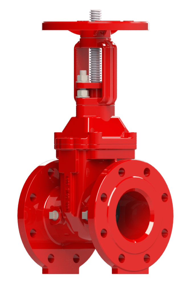
OS&Y Rising Stem Resilient Gate valve Model 203
The Century Model 203 is an Outside Screw & Yoke (OS&Y) gate valve designed to provide unambiguous, at-a-glance visual indication of its position. During operation, the threaded stem rises and lowers externally as the handwheel is turned, offering immediate confirmation of the valve’s OPEN or SHUT status. This design is the industry standard for indoor fire protection applications where quick status verification is critical. It features a fully encapsulated resilient wedge for bubble-tight sealing and a full-port waterway to minimize pressure loss.
Key Features: UL Listed, FM Approved, NSF/ANSI/CAN 61, NSF/ANSI 372, OS&Y Rising Stem for Clear Visual Indication, Resilient Wedge (EPDM), Full-Port Waterway, Fusion Bonded Epoxy Coating.
Primary Use: Main control valves for fire sprinkler systems and sectional control valves inside buildings, such as in fire pump rooms and stairway risers.
Widely used across various sectors, including: Commercial High-Rises, Hospitals, Industrial Facilities, Manufacturing Plants, and Data Centers.
Information
Proper Storage:
If storage is required before installation, position the valve upright on its base flanges. Prior to installation, re-inspect the unit to verify its condition has not changed.
Inspect for Shipping Damage:
Visually inspect the entire valve assembly for any cracks, dents, or other damage sustained during transit. Subsequently, operate the Handwheel (Item 10) through its full range of motion to confirm the Stem (Item 3) rises and lowers smoothly.
Verify External Hardware:
Confirm that all bolts, such as the SQ Bolt (Item 17) on the gland, and other external hardware are secure and have not loosened during shipment.
Handling Notice:
- Handle with care at all times to protect sealing surfaces and external components.
- Lift only by the valve Body (Item 1).
- Never lift, carry, or support the valve by its Handwheel (Item 10) or Stem (Item 3). Applying force to these components can damage the operator and compromise valve alignment.
Sitting and Orientation:
- Access and Clearance: When designing the system layout, ensure the valve is located with sufficient access for operation, adjustment, and maintenance. OS&Y valves require significant vertical clearance above the handwheel to accommodate the rising stem.
- Pipe Support: The valve must be properly supported to prevent pipeline strain on the valve Body (Item 1), which can impair performance or cause damage. Heavy valves may require independent support or anchorage.
- Installation Orientation: This valve may be installed in the following orientations:
- In horizontal pipework with the stem pointing vertically upwards.
- In vertical pipework with the stem in a horizontal position.
- Note: Installation in horizontal pipework with the stem also oriented horizontally is not recommended as it may impair shut-off performance over time.
Verify Valve Specifications:
Before installation, confirm the valve’s model, size, pressure rating, and material specifications match system engineering plans.
Prepare Mating Surfaces:
Thoroughly clean the valve flanges and both mating pipe flanges. Ensure all surfaces are free of dirt, rust, or debris that could compromise the seal.
Select and Inspect Gasket:
Use only gaskets rated for the system’s maximum operating pressure and temperature. Before installation, inspect the gasket for any defects or damage. Do not use a damaged gasket.
Align Flanges:
Position the valve between the pipe flanges, ensuring the faces are parallel and concentric.
Caution: Misalignment can impose dangerous stress on the valve Body (Item 1).
Install and Tighten Bolting:
Install all specified bolts and nuts. Tighten the bolts incrementally using a star or crisscross pattern to ensure uniform pressure on the gasket. Repeat the tightening sequence until all bolts have reached their required torque.
Perform Post-Installation Cleaning:
After completing installation and before pressurizing the system, flush the interior of the valve and piping to remove all debris.
Opening Procedure:
To open the valve, rotate the Handwheel (Item 10) counterclockwise. The Stem (Item 3) will rise, visually indicating the valve is opening. Continue until the handwheel reaches a firm stop. Once fully open, it is advantageous to rotate the handwheel clockwise approximately one-half turn.
Closing Procedure:
To close the valve, rotate the Handwheel (Item 10) clockwise. The Stem (Item 3) will lower. Continue until the handwheel reaches a firm stop.
Operational and Safety Notices:
- Prohibited Practices: Never use wheel keys, “cheater bars,” or other leverage devices on the Handwheel (Item 10). Excessive force can damage the Stem (Item 3) and other components.
- On/Off Service Only: This valve is for on/off service only. Do not use it for throttling, as this will cause wear to the Wedge (Item 2) and seats.
- Personal Protective Equipment: Operators must wear suitable hand protection when operating the valve in extreme temperature environments.
Pre-Maintenance Safety Requirements:
Before any maintenance, the valve must be fully depressurized and at ambient temperature. A full risk assessment must be completed.
Gland Packing Adjustment:
If a leak is observed from the Stem (Item 3) where it exits the Gland (Item 6), the packing may require adjustment.
- Procedure: Evenly tighten the nuts on the SQ Bolt (Item 17) in small, clockwise increments.
- Completion: Continue until the leakage stops. Warning: Do not over-tighten, as this can damage the Packing (Item 12) and score the Stem (Item 3).
Corrosion and Wall Thickness Inspection:
- Inspection Method: This check requires either removing the valve from the pipeline or removing the Bonnet (Item 4) from the Body (Item 1).
- Replacement Criteria: If wall thickness measurements indicate a material loss of 25% or more, the valve must be replaced.
By following these maintenance steps, your valve will remain in proper working condition and ready to provide service when needed most.
Please contact us at sales@centuryvalves.com for all your valve needs.
| Model 203 | ||||
|---|---|---|---|---|
| OS&Y Rising Stem Resilient Gate valve | ||||
| Connections | Flange | Mechanical Joint | Grooved | |
| Sizes | 2″, 3″, 4″, 6″, 8″, 10″, 12″, 14″, 16″, 18″, 20″, 24″ | |||
| Approvals | UL Listed, FM Approved, 14″-24″ NSF/ANSI/CAN 61, NSF/ANSI 372 | |||
| Design Standard | AWWA C515-20 | MSS-SP-70 | MSS-SP-128 | BS5163 |
| Flange Dimensions | ANSI B16.1 Class 125 Flat Face | Other Drillings Upon Request | ||
| Coating | Fusion Bond Epoxy interior and exterior to suit AWWA C550 Standard | |||
| Pressure Rating | 2″ ~ 12″ @ 365psi | 14″ ~ 18″ @ 250psi | 20″ ~ 24″ @ 200psi | |
| Temperature | -10°C to 120°C | 14°F to 248°F | ||
Certifications


We are ready to assist you
We are ready to assist you / Have questions or need support? Our team is ready to assist with your next project.