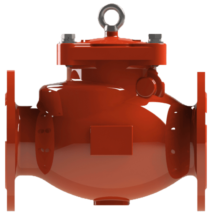
Swing Check Valve Flange End Model 870 FF
The Century Model 870 is a swing check valve designed to automatically prevent backflow by utilizing a single disc (clapper) that swings open with forward flow and closes upon flow reversal. Its primary functional feature is the bolted top-entry cover, which permits in-line access for inspection and maintenance of internal components without removing the valve body from the pipeline.
Key Features: UL Listed, FM Approved, Flanged or Grooved Ends, Unobstructed Waterway, Top-Entry Cover for In-Line Servicing.
Primary Use: Backflow prevention in fire pump discharge lines, city water connections, and at the base of fire sprinkler risers.
Widely used across various sectors, including: Commercial Buildings, Industrial Facilities, Municipal Water Systems, and Power Generation Plants.
Information
Proper Storage: If storage is required, keep the valve in a cool, dry environment with end protectors in place. Before installation, re-inspect the unit to verify its condition has not changed.
Inspect for Shipping Damage:
- Visually inspect the entire valve assembly for any cracks, dents, or other damage.
- Confirm that all bolts and nuts on the cover (Item 1) are secure and have not loosened.
Internal Inspection:
- CRITICAL: Before installation, look inside the valve to locate and remove any wooden or paper chocks. These are fitted during shipping to prevent the disc (Item 11) from moving and must be removed for the valve to function.
- Ensure the valve interior is clean and free from any foreign matter.
Handling Notice:
- This is a heavy-duty assembly. Handle with care at all times.
- For large valves, use the provided lifting eye bolt to lift the unit.
- Lift the unit only by the main body (Item 6).
Verify Valve Specifications: Before installation, confirm that the valve’s model (870-F or 870-G), connection type, size, and pressure rating match the requirements listed in the system engineering plans.
Layout and Siting:
- Horizontal Installation: The valve must be installed with the bolted cover (Item 1) positioned upright and level. This is the standard and preferred orientation.
- Vertical Installation: The valve may be installed in a vertical pipeline only if the flow is in an upwards direction.
- PROHIBITED: Never install a check valve in a vertical pipeline with downward flow. The valve will not function correctly.
- Adjoining pipework must be properly supported to prevent pipeline strain on the valve body.
- Flow Direction: The valve body (Item 6) features a cast-in arrow indicating the direction of flow. The valve must be installed so this arrow corresponds with the direction of flow in the pipeline.
INSTALLATION PROCEDURE – FLANGED (MODEL 870-F)
- Prepare Surfaces: Thoroughly clean the valve flanges and the mating pipe flanges. Ensure all surfaces are completely free of dirt, rust, or debris.
- Select and Inspect Gasket: Use a new gasket that is correctly sized for the flange and rated for the system’s operating conditions. Inspect the gasket for any defects before use.
- Flange Alignment and Bolting:
- Position the valve between the pipe flanges, ensuring the flanges are parallel and concentric before making contact with the gasket.
- Caution: Misalignment can impose dangerous stress on the valve body (Item 6), leading to damage or failure.
- Install all specified flange bolts and nuts. Tighten the nuts incrementally using a star or crisscross pattern to ensure uniform pressure on the gasket. Repeat the sequence until all bolts have reached their required torque.
INSTALLATION PROCEDURE – GROOVED (MODEL 870-GG)
- Prepare Mating Surfaces: Thoroughly clean the valve’s grooved ends and the mating pipe grooves. Ensure all surfaces are free of dirt, rust, or debris.
- Select and Inspect Gasket: Use a new grooved coupling gasket that is correctly sized and rated for the system’s operating conditions. Inspect the gasket for any defects before use.
- Coupling Installation:
- Apply a thin, even layer of an approved lubricant to the gasket. Place the lubricated gasket over one pipe end.
- Align the valve with the pipe ends and slide the gasket into position, centering it over the joint.
- Install the two halves of an approved grooved coupling into the pipe and valve grooves. Insert bolts and hand-tighten the nuts.
- Tighten the nuts incrementally and evenly using an alternating pattern until the coupling housing achieves metal-to-metal contact as specified by the coupling manufacturer.
- System Flushing: After completing the installation and before pressurizing the system, thoroughly flush the interior of the valve and piping to remove all installation debris.
Operation: Century Check Valves are designed to operate automatically. They activate without any external assistance, opening with the forward flow of water and closing when the flow stops or reverses to prevent backflow. No manual operation is required.
Maintenance: While regular maintenance is not typically required, following these procedures should service be necessary.
Pre-Maintenance Safety:
- Before any inspection or maintenance, the valve and associated piping must be fully isolated, depressurized to zero pressure, and drained.
- A full risk assessment must be completed before beginning work.
Cover Gasket Replacement:
- Ensure the system is isolated and drained.
- Loosen and remove the nuts and bolts from the Cover (Item 1).
- Carefully remove the cover. If it is stuck, gently tap with a rubber mallet to release.
- Examine the internal parts (Disc (Item 11), Rocker (Item 7), Seat (Item 12)) for proper movement and to ensure they are free from obstruction.
- Remove the old gasket and thoroughly clean the sealing surfaces on the Cover (Item 1) and Body (Item 6).
- Place a new cover gasket in position.
- Carefully reposition the cover, ensuring the new gasket is not displaced.
- Replace the nuts and bolts, tightening them in a star or crisscross pattern.
By following these maintenance steps, your valve will remain in proper working condition and ready to provide service when needed most.
Please contact us at sales@centuryvalves.com for all your valves needs.
| Model 870 FF | ||||||
|---|---|---|---|---|---|---|
| Swing Check Valve Flange End | ||||||
| Connections | Flange | |||||
| Sizes | 2″, 2 1/2″, 3″, 4″, 6″, 8″, 10″, 12″ | |||||
| Approvals | UL 1091, FM1112 | |||||
| Design Standard |
|
|||||
| Flange Dimensions | ANSI B16.1 Class 125 | Other Drillings Upon Request | ||||
| Coating | Fusion Bond Epoxy interior and exterior to suit AWWA C550 Standard | |||||
| Pressure Rating | 2″ ~ 12″ @ 300psi | |||||
| Temperature | -10°C to 120°C | 14°F to 248°F | ||||
Certifications


We are ready to assist you
We are ready to assist you / Have questions or need support? Our team is ready to assist with your next project.