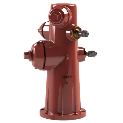
Wet Barrel Hydrant Model F800
The Century Model F800 is a wet barrel fire hydrant designed for service in non-freezing climates. In this design, the hydrant barrel is constantly filled with water and under system pressure. Each outlet is controlled by its own independent valve and operating nut, allowing for multiple, individually controlled connections. This configuration provides immediate water access without the need to operate a main underground valve, making it ideal for rapid deployment in emergency situations.
Key Features: UL Listed, FM Approved, Wet Barrel Design (AWWA C503), Independent Valve Control for Each Nozzle, Simple and Robust Construction.
Primary Use: Fire protection water access in regions where freezing is not a concern.
Widely used across various sectors, including: Municipal Fire Departments in Warmer Climates, Coastal Regions, Industrial Facilities, and Airports.
Information
Pre-Installation Checks
Before installation, verify the following:
- Model Confirmation: Ensure the delivered hydrant is the correct model: Century F800.
- Outlet Nozzles: Verify the correct size for both the pumper and hose outlets (Item 5 & 23).
- Inlet Flange: Confirm the correct bolt pattern for the bottom ANSI 6” flange.
- Valve Stem Operation: Cycle each valve stem from closed to fully open and back to closed to ensure smooth operation. Difficult operation indicates the need for valve repairs.
- External Fasteners: Ensure all external bolts and nuts are tightened (Item 13 & 20).
- Inlet Inspection: If the inlet flange cover is damaged or removed, inspect the inside of the hydrant body (Item 1) for foreign materials. Keep the inlet flange covered until the moment of installation.
Hydrant location and setback:
Proper hydrant placement is critical to prevent damage from vehicles. In areas without local codes, the American Water Works Association (AWWA M17) recommends a minimum setback of 2 feet (610 mm) from the face of the curb to the nearest point on the hydrant. In rural areas without curbs, this setback should be increased to ensure the hydrant remains protected but accessible to firefighting equipment.
Concrete Thrust Collar for Traffic Models:
If installing a Century traffic model hydrant, a concrete thrust collar must be installed at the ground bury line to absorb and disperse the force from a vehicle impact.
- Thrust Collar Dimensions: The collar should be a minimum of 2 feet in diameter (610 mm) and 6 inches thick (152.4 mm). The size must be increased in soil with poor load-bearing capacity (e.g., loose or sandy soil) to ensure stability.
Hydrant Connection to the Water Main:
The Century hydrant must be connected to a water main capable of delivering the required fire flow. Refer to AWWA C600 standards for the installation of ductile-iron water mains and their appurtenances.
- Isolation Valve: An isolation valve must be installed between the hydrant and the water main. This allows the hydrant to be taken out of service for maintenance or repair without disrupting the entire water system.
Hydrant Placement and Alignment:
- Vertical Installation: Install the hydrant as vertically as possible to ensure correct and stable operation.
- Maintenance Clearance: Maintain adequate clearance around the ground line to allow easy access to the flange bolts for maintenance or removal.
- Nozzle Orientation: The pumper outlet nozzle (Item 5) should face the curb for fast, unobstructed access from the street. Ensure the hydrant is not blocked by street furniture, signs, poles, or trees.
Obstructions and Accessibility:
The area around the hydrant must be kept clear of any obstacles that could prevent immediate access to the nozzle caps (Item 4 & 22) and operating nuts (Item 19). Any delay in accessing the hydrant during a fire can have severe consequences.
Commissioning and testing:
Hydrant Flushing:
After installation, the hydrant must be thoroughly flushed to remove any dirt, debris, or construction residue from the hydrant and connecting pipework. This ensures a clean water supply and prevents damage to the internal hydrant components.
Debris Check:
When first closing the valves, listen and feel for any grinding or blockage that could indicate debris lodged in the valve opening. Debris can prevent the valve disc (Item 10 & 27) from seating correctly, causing leaks and operational failure.
Final Checks:
Securely tighten all hydrant nozzle caps (Item 4 & 22) so they cannot be removed by hand. Ensure the main auxiliary valve is left in the fully open position so the hydrant is ready for service.
Record Keeping:
Initiate a detailed record for the newly installed hydrant, including: location, installation date, model, nozzle/nut sizes, and flow data (if available).
Pressure testing procedures:
Test 1: Pressure Testing at Main Line Pressure:
This test checks for leaks under normal operating conditions.
- Close Auxiliary Valve: Close the auxiliary valve to isolate the hydrant.
- Remove Nozzle Cap: Remove a nozzle cap (e.g., Item 4) and slightly open the corresponding hydrant valve to allow air to vent.
- Fill and Purge: Slowly open the auxiliary valve, allowing water to fill the hydrant and purge all air through the open valve.
- Caution: Trapped, compressed air can be a safety hazard. Always vent air slowly and completely.
- Pressurize Hydrant: Once a steady stream of water flows from the nozzle, close the hydrant valve. Fully open the auxiliary valve to pressurize the hydrant to line pressure.
- Inspect for Leaks: With the hydrant pressurized, check for leaks at flange joints, nozzles (Item 5 & 23), disc/sealing rings (Item 10/27 & 9/26), and glands (Item 7 & 25).
- Repair and Retest: If any leaks are found, depressurize the hydrant and replace the faulty components (e.g., O-Rings (Item 3, 17, 18, 21), Gaskets (Item 6 & 24), or Discs (Item 10 & 27)). Repeat the pressure test to confirm the repair.
Test 2: Pressure Testing Above Main Line Pressure (Rated Working Pressure):
This test ensures the hydrant’s integrity at its maximum working pressure.
- Connect Test Pump: With the auxiliary valve closed, connect a pressure test pump to a hose nozzle (Item 23).
- Vent Air: Vent all air from the hydrant by slightly opening the top valve.
- Open Hydrant Valve: Open the hydrant valve connected to the test pump.
- Operate Pump: Slowly operate the pump to bring the hydrant to the required test pressure.
- Inspect for Leaks: At full test pressure, inspect the same critical areas for leaks.
- Repair and Retest: If leaks are detected, repair as needed and repeat the test.
- Return to Service: Once the test is complete, close the valve at the test pump, slowly open the auxiliary valve, and return the hydrant to service.
Routine inspection and maintenance:
A routine inspection and maintenance program is essential for hydrant reliability.
Annual Inspection and Operation Procedure:
- Visual Inspection: Check the hydrant’s exterior for damage, corrosion, and leaks. Inspect the condition of the paint on the body (Item 1).
- Caps and Chains: Remove nozzle caps (Item 4 & 22). Check that cap chains (Item 2) are secure and untangled. Clean nozzle threads and apply a non-toxic, anti-seize compound.
- Isolate and Exercise: Close the auxiliary valve. Fully open and close each hydrant valve twice using the operating nut (Item 19) to ensure the stems move freely and clear any mineral deposits.
- Leak Check: While the hydrant is isolated, visually inspect the valve discs (Item 10 & 27) through the nozzle openings for damage or excessive indentation from the seat.
- Repressurize and Vent: With the hydrant valves closed, slowly open the auxiliary valve to repressurize the hydrant, leaving one top cap off and its valve slightly open to vent air. Once water flows, close the valve.
- Flow Test: Attach a diffuser or short hose. Fully open and close each nozzle one at a time to confirm strong, clear flow and proper valve operation.
- Final Steps: Close all valves. Replace and tighten all nozzle caps by hand. Ensure the auxiliary valve is left in the fully open position.
- Record: Document all maintenance actions, findings, and any follow-up repairs required.
Recommendations:
- Spare Parts: Maintenance crews should carry common spare parts, such as chains (Item 2), caps (Item 4 & 22), and gaskets (Item 6 & 24), for immediate repairs.
- Flow Measurement: Periodically conduct and record flow tests as described in AWWA M17 to monitor system performance.
By following these maintenance steps, the Wet Barrel hydrant will remain in proper working condition and ready to provide water when needed most.
Please contact us at sales@centuryvalves.com for all your hydrant needs.
| Model F800 | ||||||
|---|---|---|---|---|---|---|
| Wet Barrel Hydrant | ||||||
| Connections | Two hose nozzles 2 1/2″ NHT, One pumper nozzle 4 1/2″ NHT – Other configurations available | |||||
| Approvals |
|
|||||
| Design Standard | AWWA C503 | |||||
| Flange Inlet | 6″ Flange Inlet Connection to AWWA C110/ANSI B16.1, Class 125 or B16.5, Class 150 RF drilling Pattern | |||||
| Coating | Fusion Bond Epoxy interior and exterior to suit AWWA C550 Standard | |||||
| Pressure Rating | 250psi | |||||
| Temperature |
|
|||||
Certifications


We are ready to assist you
We are ready to assist you / Have questions or need support? Our team is ready to assist with your next project.